Here is a simple, clear, and complete beginner tutorial to help you start programming FPGAs using VHDL — ideal even if you’ve never used VHDL before.
This guide walks you from zero → first blinking LED project → simulation → bitstream → hardware programming.
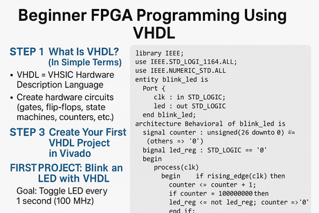
STEP 1 — What Is VHDL? (In Simple Terms)
VHDL = VHSIC Hardware Description Language
You use VHDL to describe hardware circuits, not algorithms.
That means you are creating:
- Gates
- Flip-flops
- State machines
- Counters
- Registers
VHDL code becomes a real circuit inside your FPGA.STEP 2 — Install Tools (FREE)
If using Xilinx/AMD FPGA boards:
➡️ Install Vivado WebPACK (free).
https://www.xilinx.com/support/download.html
Works for:
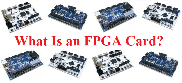
- Basys 3
- Nexys A7
- Arty A7
- PYNQ boards
If using Intel/Altera boards:
➡️ Install Quartus Prime Lite.
STEP 3 — Create Your First VHDL Project in Vivado
- Open Vivado
- File → New Project
- Create RTL Project
- Add VHDL file
- Select your FPGA board (e.g., Basys3 = xc7a35tcpg236-1)
STEP 4 — Learn the BASIC Structure of VHDL
A VHDL file has two parts:
1. ENTITY → Inputs/Outputs
entity blink_led is
    Port (
        clk : in STD_LOGIC;
        led : out STD_LOGIC
    );
end blink_led;
✔️ 2. ARCHITECTURE → Behavior
architecture Behavioral of blink_led is
begin
    -- your logic here
end Behavioral;
That’s the skeleton of every VHDL module.
STEP 5 — FIRST PROJECT: Blink an LED with VHDL
This is the FPGA “Hello World”.
🧩 Goal:
Toggle LED every 1 second using a 100 MHz clock.
⭐ Full Working VHDL Code
library IEEE;
use IEEE.STD_LOGIC_1164.ALL;
use IEEE.NUMERIC_STD.ALL;

entity blink_led is
    Port (
        clk : in STD_LOGIC;        -- 100 MHz clock input
        led : out STD_LOGIC        -- LED output
    );
end blink_led;

architecture Behavioral of blink_led is
    signal counter : unsigned(26 downto 0) := (others => '0');
    signal led_reg : STD_LOGIC := '0';
begin

    process(clk)
    begin
        if rising_edge(clk) then
            counter <= counter + 1;

            if counter = 100000000 then
                led_reg <= not led_reg;
                counter <= (others => '0');
            end if;
        end if;
    end process;

    led <= led_reg;

end Behavioral;
STEP 6 — Apply Constraints (.xdc File)
You must tell Vivado which FPGA pin drives the LED.
Example for Basys 3:
set_property PACKAGE_PIN U16 [get_ports {led}]
set_property IOSTANDARD LVCMOS33 [get_ports {led}]
For clock (100 MHz):
set_property PACKAGE_PIN W5 [get_ports {clk}]
set_property IOSTANDARD LVCMOS33 [get_ports {clk}]
create_clock -period 10.00 -name sys_clk_pin -waveform {0 5} [get_ports clk]
STEP 7 — Simulate the VHDL (HIGHLY Recommended)
To simulate:
- Create a testbench file (no ports in entity).
- Instantiate your module.
- Create a clock signal.
✔️ Example Testbench:
library IEEE;
use IEEE.STD_LOGIC_1164.ALL;
use IEEE.NUMERIC_STD.ALL;

entity tb_blink is
end tb_blink;

architecture behavior of tb_blink is

    signal clk : STD_LOGIC := '0';
    signal led : STD_LOGIC;

begin

    -- Instantiate the Unit Under Test (UUT)
    uut: entity work.blink_led
        port map (
            clk => clk,
            led => led
        );

    -- Clock generation (10 ns period = 100 MHz)
    clk <= not clk after 5 ns;

end behavior;
- Run simulation
- View the waveform
You should see led toggling.
TEP 8 — Synthesize → Implement → Generate Bitstream
In Vivado:
✔️ Run Synthesis
✔️ Run Implementation
✔️ Generate Bitstream
Vivado will show:
- timing
- routing
- resource usage
STEP 9 — Program the FPGA Board
- Open Hardware Manager
- Connect board via USB
- Autodetect device
- Select the generated
.bitfile - Click “Program”
Your LED will blink 🎉
Congratulations — you've programmed your first FPGA with VHDL!
STEP 10 — Recommended Beginner Projects (in VHDL)
🟦 1. Button-Controlled LED
- Read push button
- Turn LED on/off
Concepts:
- debouncing
- input signals
🟩 2. 4-bit Counter on LEDs
0000 → 1111Concepts:
- registers
- binary counting
🟨 3. 7-Segment Display Driver
Display 0–9.
Concepts:
- combinational logic
- decoders
🟧 4. PWM Signal Generator
Control LED brightness.
Concepts:
- duty cycle
- fast counters
🟥 5. UART Transmitter/Receiver
Communicate with PC serial port.
Concepts:
- baud rate
- sampling
- state machines
⭐ After these projects you will understand:
✔️ VHDL syntax and structure
✔️ Clocked vs combinational processes
✔️ Signals and variables
✔️ Constraints and pin mapping
✔️ Simulation and debugging
✔️ Timing and clock domains
✔️ Real hardware implementation







💬 Comments
No comments yet. Be the first to comment!
Login to comment.